6. Traction Transformer:
Traction transformer is used to step down the available 25 kV AC OHE voltage in the range of 1000 volts. The output of transformer secondary winding is connected to the input of single phase four quadrant traction converter through a contactor. During the operation of 4QC converter, the output voltage supply of traction transformer secondary winding is short circuited through IGBTs for a short time ( "ON" and "OFF" frequency of IGBT is kept in order of few KHz ) and re-open circuit to develop high voltage pulse equivalent to ‘Ldi/dt’ at the input of 4QC converter. Thus, the DC link voltage at the output of single phase 4QC converter can be boost up based on the operational requirement. To facilitate above activity, the traction transformer accompanied by 4QC converter are designed to achieve percentage impedance of around 40%. However, the traction transformer of conventional AC locomotive is designed for low value of percentage impedance (less than 10%) to achieve better voltage regulation from no load to full load. The percentage impedance of a transformer is the volt drop on full load due to the winding resistance and leakage reactance expressed as a percentage of the rated voltage. The higher percentage impedance of transformer can be achieved by increasing the air gap between transformer winding and core. The low voltage winding of traction transformer is kept near to the iron core to reduce the overall insulation cost. In regenerative braking mode, traction transformer works as step up transformer and feed power from transformer to OHE system. The transformer is equipped with various protections like over pressure, over temperature, oil flow detection, oil level detection etc.
7. Current Transformer:A current transformer (CT) is used in electrical power system for stepping down alternating current of the system for metering and protection purpose in a convenient way. The primary winding of CT may be of either a single flat turn, or just a conductor or bus bar placed through a central hole and secondary winding consists of thousand turns of thin insulated wire. Thus, CT should not be kept in open circuit condition during the operation; otherwise, high voltage will be induced in secondary winding of CT, which may damage the insulation of CT. Most current transformers have a standard secondary rating of 1A or 5A. Generally, CTs are rated as 100/5A means that the primary current is 20 times greater than the secondary current, so when 100A is flowing in the primary conductor it will result in 5A flowing in the secondary winding. For an ideal CT, the angle between the primary and reversed secondary current vector should be zero. But for an actual CT, there is always a difference in phase between primary & secondary winding due to the fact that primary current has to supply the component of the exiting current. The angle between the primary and reversed secondary current phases is termed as phase angle error in current transformer. Similarly, primary current does not exactly equal to the secondary winding current multiplied by turns ratio because primary current has to contribute the core excitation current. This error in current transformer is called ratio error. Error in Current Transformer can be reduced using a core of high permeability and low hysteresis loss magnetic materials.
8. Single Phase Four Quadrant Traction Converter:
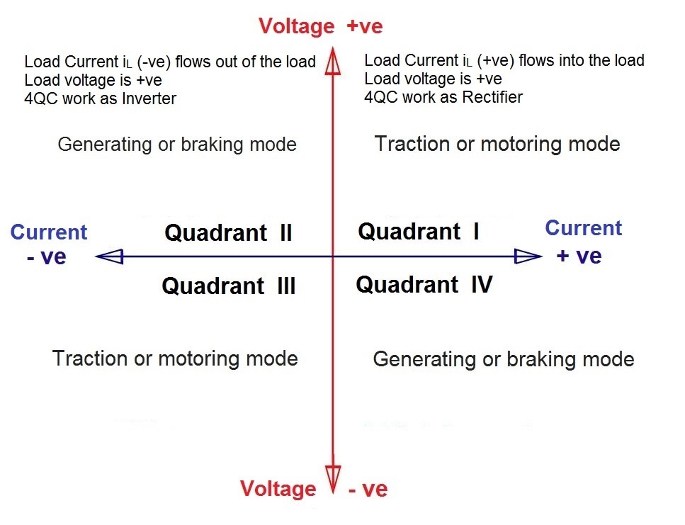
The output of traction transformer is supplied to the single phase four quadrant traction converter through a contactor. Each leg of 4QC converter consists of silicon based Insulated Gate Bipolar Transistor (IGBT) with anti-parallel arrangement of power diode. A four-quadrant stage is the dedicated part of a power converter used to manage load voltage and current in the four-quadrant area. Basically, the design of 4QC is based on two controlled switching device's bridges mounted in anti parallel arrangement. During the traction or motoring mode, the 4QC works as boost converter (i.e. step-up) and convert the single phase AC supply available at the transformer secondary into controlled DC voltage for the DC link. The term 4QC signifies that the phase angle between voltage and current is freely adjustable while motoring as well as braking. During train operation, single phase 4QC operates in first quadrant (during traction or motoring mode) and second quadrant (during generating or braking mode) only. The polarity of the DC link remains fixed during the operation of traction motor in all four quadrants.
Traction transformer is used to step down the available 25 kV AC OHE voltage in the range of 1000 volts. The output of transformer secondary winding is connected to the input of single phase four quadrant traction converter through a contactor. During the operation of 4QC converter, the output voltage supply of traction transformer secondary winding is short circuited through IGBTs for a short time ( "ON" and "OFF" frequency of IGBT is kept in order of few KHz ) and re-open circuit to develop high voltage pulse equivalent to ‘Ldi/dt’ at the input of 4QC converter. Thus, the DC link voltage at the output of single phase 4QC converter can be boost up based on the operational requirement. To facilitate above activity, the traction transformer accompanied by 4QC converter are designed to achieve percentage impedance of around 40%. However, the traction transformer of conventional AC locomotive is designed for low value of percentage impedance (less than 10%) to achieve better voltage regulation from no load to full load. The percentage impedance of a transformer is the volt drop on full load due to the winding resistance and leakage reactance expressed as a percentage of the rated voltage. The higher percentage impedance of transformer can be achieved by increasing the air gap between transformer winding and core. The low voltage winding of traction transformer is kept near to the iron core to reduce the overall insulation cost. In regenerative braking mode, traction transformer works as step up transformer and feed power from transformer to OHE system. The transformer is equipped with various protections like over pressure, over temperature, oil flow detection, oil level detection etc.
7. Current Transformer:A current transformer (CT) is used in electrical power system for stepping down alternating current of the system for metering and protection purpose in a convenient way. The primary winding of CT may be of either a single flat turn, or just a conductor or bus bar placed through a central hole and secondary winding consists of thousand turns of thin insulated wire. Thus, CT should not be kept in open circuit condition during the operation; otherwise, high voltage will be induced in secondary winding of CT, which may damage the insulation of CT. Most current transformers have a standard secondary rating of 1A or 5A. Generally, CTs are rated as 100/5A means that the primary current is 20 times greater than the secondary current, so when 100A is flowing in the primary conductor it will result in 5A flowing in the secondary winding. For an ideal CT, the angle between the primary and reversed secondary current vector should be zero. But for an actual CT, there is always a difference in phase between primary & secondary winding due to the fact that primary current has to supply the component of the exiting current. The angle between the primary and reversed secondary current phases is termed as phase angle error in current transformer. Similarly, primary current does not exactly equal to the secondary winding current multiplied by turns ratio because primary current has to contribute the core excitation current. This error in current transformer is called ratio error. Error in Current Transformer can be reduced using a core of high permeability and low hysteresis loss magnetic materials.
8. Single Phase Four Quadrant Traction Converter:
The output of traction transformer is supplied to the single phase four quadrant traction converter through a contactor. Each leg of 4QC converter consists of silicon based Insulated Gate Bipolar Transistor (IGBT) with anti-parallel arrangement of power diode. A four-quadrant stage is the dedicated part of a power converter used to manage load voltage and current in the four-quadrant area. Basically, the design of 4QC is based on two controlled switching device's bridges mounted in anti parallel arrangement. During the traction or motoring mode, the 4QC works as boost converter (i.e. step-up) and convert the single phase AC supply available at the transformer secondary into controlled DC voltage for the DC link. The term 4QC signifies that the phase angle between voltage and current is freely adjustable while motoring as well as braking. During train operation, single phase 4QC operates in first quadrant (during traction or motoring mode) and second quadrant (during generating or braking mode) only. The polarity of the DC link remains fixed during the operation of traction motor in all four quadrants.
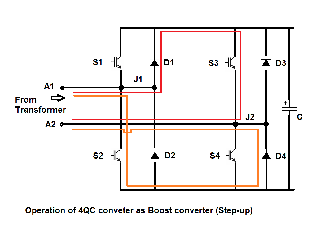
During generating or braking mode, 4QC takes current (energy) from DC link and converts it into the single phase AC supply, so the same can be fed back to the OHE system through main transformer. During the operation of 4QC as boosting converter, the two IGBTs S2 & S3 are switched ‘ON’ simultaneously (IGBTs S1 & S4 are kept switched ‘OFF’) for a short duration in positive half wave of AC supply. When IGBTs are switched ‘ON’, a short circuit current flow through the secondary winding of transformer and follow the paths – A1,J1,D1,S3,J2,A2 and A1,J1,S2,D4,J2,A2 respectively in positive half wave of AC supply. As soon as the current has reached the desired value of IGBT, it is switched ‘OFF’. This induces a high voltage pulse (equivalent to the Ldi/dt, where L is the self-inductance of the transformer) and the same applied to the DC link capacitor through the diodes. Capacitors oppose the rise in applied voltage and consequently current flow from transformer to DC link which charge the DC link at high voltage. Similarly, IGBTs S1 & S4 are switched ‘ON’ simultaneously (IGBTs S2 & S3 are kept switched ‘OFF’) for a short duration in negative half wave of AC supply. When IGBTs are switched ‘ON’, a short circuit current flow through the secondary winding of transformer and follow the paths – A2,J2,S4,D2,J1,A1 and A2,J2,D3,S1,J1,A1 respectively in negative half wave of AC supply. The switching frequency of the IGBTs is kept in order of few KHz. As a consequence, current continue to flow in DC link circuit, through freewheeling diodes and the output voltage of DC link is maintained more than the maximum value of input AC supply. The power factor at traction transformer input can also be improved by adopting suitable switching pattern of IGBTs.
Before the development of IGBT, Gate Turn Off (GTO) thyristor was used as high-power semiconductor switching device. Like thyristor, a GTO is a current controlled, minority carrier, bipolar device which consist of four p-n-p-n layers & three junctions. A GTO can be turned on by a gate signal, and can also be turned off by a gate signal of negative polarity. GTO thyristors suffer from long switch off time and this restricts the maximum switching frequency of GTO to approximate 1 kHz only. Additional snubber circuits are also required to limit the di/dt, dv/dt parameters during turn-on and turn-off. MOSFET is also a switching device and suitable for low power Switched Mode Power Supply(SMPS), works at low voltage and high switching frequency circuit (>200kHz). MOSFET has low switching loss but its on state resistance per unit area is high which results into higher conduction loss. On the other hand, bipolar junction transistor (BJT) has higher switching losses but lower conduction losses. An insulated-gate bipolar transistor (IGBT) combines the advantage of MOSFET and BJT. IGBT combines an isolated-gate FET for the control input and a bipolar power transistor as a switch in a single device. Gate control circuit of IGBT is much simpler and requires low control power. No snubber circuit is required for IGBT operation. IGBT is a suitable switching device in the frequency range of 1KHz to 10 KHz. Due to above advantages, IGBT has replaced GTO from the traction system. The IGBT is used in medium to high-power applications like switched-mode power supplies, traction motor control and induction heating etc. A single chip of IGBT has voltage rating of approximate 1.1 KV. A module of IGBT may have more than one IGBT chip connected in series-parallel connections. IGBT modules are available in the voltage range of 1.8KV, 3.3KV, 4.5KV & 6.5 KV with current rating upto 1200A. The switching loss of IGBT contributes major portion of the total losses and its value increases with increase in switching frequency, however conduction loss of IGBT depends on the load current.During the generating or braking mode, power flow in reverse direction i.e. from DC link to OHE system. Now, single phase 4QC converter works as pulse width modulation (PWM) inverter and converter DC link voltage into alternating supply voltage of 50Hz (equal to OHE supply frequency). The same alternating voltage is step-up by the main transformer and feed back to the OHE system.
9. DC Link:
Adequate capacity of capacitor bank is placed at the DC link to reduce the ripple content of the DC voltage. A dc voltage sensor is also installed at DC link to measure its voltage for control and safety purpose. A bleeder resistance is also connected in parallel to discharge the DC link capacitor. The DC output of single phase 4QC converter stores energy in the capacitor bank. This provides the stiff supply voltage on DC link and allow the use of voltage source inverter (VSI) at the output of DC link. The vast majority of drives are VSI type with PWM voltage output. In metro train, the DC link voltage is selected in the range of 1500V DC.
10. Three Phase Four Quadrant Traction Converter:
During the traction or driving mode, three phase 4QC converter works as voltage source inverter and convert DC link supply into three phase AC supply voltage of variable magnitude as well as variable frequency. The output of the 4QC inverter is fed to the three phase induction motors. The maximum possible amplitude of the phase-to-phase output voltage depends upon the magnitude of the DC link voltage and the modulation index. When the reference modulating signal is a sinusoid of amplitude Am, and the amplitude of the triangular carrier wave is Ac, the ratio of ‘Am/Ac’ is known as the modulation index. The modulation index controls the amplitude of the output voltage and harmonic content in the output voltage. However, the modulation ratio is the ratio between the frequency of the triangular carrier wave to the frequency of the reference modulating wave ‘fc/fm’. Modulation ratio is related to the dominant harmonic frequency in output voltage. The RMS value of the output voltage can be controlled by varying the modulation index and frequency of the output voltage can be increased by increasing the frequency of the reference modulating signal wave.
